AKTAKOM ACM-2368 Professional True RMS 1000A AC/DC Clamp Meter provides accurate inrush current measurement.
Features
1. 6600 counts digital LCD display with backlit
2. Electronic overload protection
3. Auto Power Off and Low battery indication
4. Data Hold function
5. True RMS AC Voltage and Current
6. Inrush current measurement and DCA Zero
7. Analog Bargraph Segments
8. Continuity buzzer & Diode check
9. AC/DC Current
10. DCA Zero function
Data Hold Button
To freeze the LCD meter reading, press the data HOLD button. While data hold is active, the HOLD icon appears on the LCD. Press the HOLD button again to return to normal operation.
LCD Backlight Button
The LCD is equiped with backlighting for easier viewing, especailly in dimly lit areas. Press the backlight button to turn the backlight on. Press again to turn the backlight off. Note that the meter does have an auto power off feature as described below.
Inrush
The inrush current function for AC current measurement detects the starting-up current of a motor. In ACA mode press INRUSH button, that will for make the meter enter INRUSH mode. Then LCD will displays“----”until the motor is starting up and detected. The detection will be done only one time and the output reading will be hold. To exit INRUSH mode press, INRUSH button more than one second.
Specifications
|
Function
|
Range & Resolution
|
Accuracy (% of reading)
|
|
AC Current
|
660.0 AAC
|
± (2.5% +8digits)
|
|
1000 AAC
|
± (2.8% +8digits)
|
|
DC Current
|
660.0 ADC
|
± (2.5% +5digits)
|
|
1000 ADC
|
± (2.8% +8digits)
|
|
DC Voltage
|
6.600 VDC
|
± (1.5% + 3 digits)
|
|
66.00 VDC
|
|
600.0 VDC
|
|
AC Voltage
|
6.600 VAC
|
± (1.8% + 5 digits)
|
|
66.00 VAC
|
|
600.0 VAC
|
|
Resistance
|
660.0 Ω
|
± (1.0% + 4 digits)
|
|
6.600KΩ
|
± (1.5% + 2 digits)
|
|
66.00KΩ
|
|
660.0KΩ
|
|
6.600MΩ
|
± (2.5% + 3 digits)
|
|
66.0MΩ
|
± (3.5% + 5 digits)
|
|
Frequency
|
30Hz to 15KHz
|
±(1.2% reading + 2 digits)
Sensitivity: 30~5kHz:10Vrms min.
5kHz~15kHz:40Vrms min.
@ 20% to 80% duty cycle
|
|
Duty Cycle
|
10.0 to 94.9%
|
±(1.2% reading + 2 digits)
|
Pulse width: 100µs - 100ms, Frequency: 30Hz to 15kHz;
Sensitivity: 30~5kHz:10Vrms min.5kHz~15kHz:40Vrms min.
|
Temp
(type-K)
(probe accuracy not included)
|
-20 to 760°C
|
±(3.0% reading + 5 °C)
|
|
-4 to 1400°F
|
±(3.0% reading + 9°F)
|
Diode Test Test current of 0.3mA typical; Open circuit voltage 3V DC typical.
Continuity Check Threshold <40W; Test current < 0.5mA
Size(H×W×D): 9in
× 3,2in
× 2in / 229mm
× 80mm
× 49mm
Weight: 10,7oz / 303g
Accessories
1. 9V Battery

2. Test leads

3. Type K Temperature probe

4. User manual

5. Gift box with carrying case

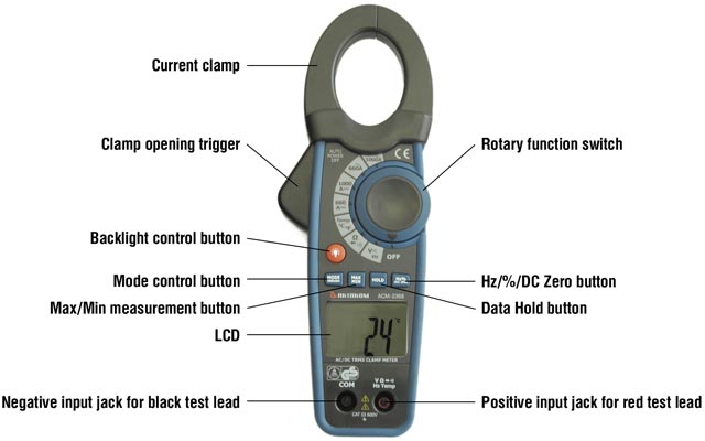
Controls of ACM-2368 Clamp Meter
AC/DC Current Measurement
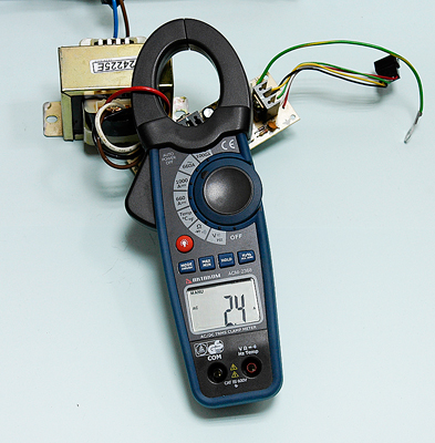
- Ensure that the test leads are disconnected from the meter before making current clamp measurements
- Set the Function switch to the 1000A or 660A range. If the approx. range of the measurement is not known, select the highest range then move to the lower ranges if necessary
- Press the DC ZERO button to zero the meter display
- Press the trigger to open jaw. Fully enclose only one conductor. For optimum results center the conductor in the jaw
- The clamp meter LCD will display the reading.
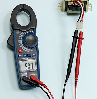
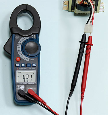
AC/DC Voltage Measurement
- Insert the black test lead into the negative COM terminal and the red test lead into the positive V·Ω·TEMP·Hz terminal
- Set the function switch to the V Hz position
- Use the MODE button to select AC or DC Voltage
- Connect the test leads in parallel to the circuit under test
- Read the voltage measurement on the LCD display.
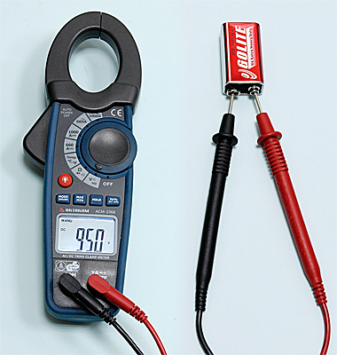
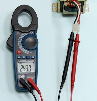
Continuity Measurements
- Insert the black test lead into the negative COM terminal and the red test lead into the VΩTEMPHz positive terminal.
- Set the function switch to the
 position.
- Use the MODE button to select continuity
 . The display icons will change when the MODE button is pressed.
- Touch the test probe tips across the circuit or component under test.
- If the resistance is < 40Ω, a tone will sound.
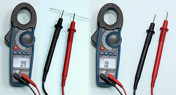
Diode Test
- Insert the black test lead banana plug into the negative COM jack and the red test lead banana plug into the V·Ω·TEMP·Hz· positive jack
- Turn the function switch to position. Use the MODE button to select the diode function if necessary (diode symbol will appear on the LCD when in Diode test mode)
- Touch the test probe tips to the diode or semiconductor junction under test. Note the meter reading
- Reverse the test lead polarity by reversing the red and black leads. Note this reading
- The diode or junction can be evaluated as follows:
- If one reading displays a value (typically 0.400V to 0.900V) and the other reading displays OL, the diode is good.
- If both readings display OL the device is open.
- If both readings are very small or ‘0’, the device is shorted.
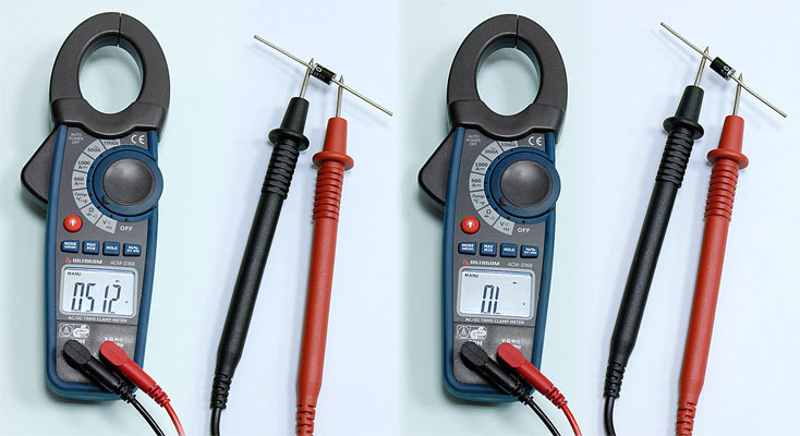
Frequency or % duty cycle measurements
- Insert the black test lead banana plug into the negative COM jack and the red test lead banana plug into the V·Ω·TEMP·Hz· positive jack.
- Set the function switch to the V Hz Position.
- Press the Hz/% button to select the Frequency (Hz) or Duty Cycle (%) function.
- Touch the test probe tips across the part under test.
- Read the Frequency value on the display.
- Duty cycle measurement: When the duty cycle is less than 10.0%, the LCD panel shows UL. When the duty cycle is more than 94.9%, the LCD panel shows OL.
- The display will indicate the proper decimal point and value.
- Press the Hz/% button again to return to the voltage mode.
Resistance Measurement
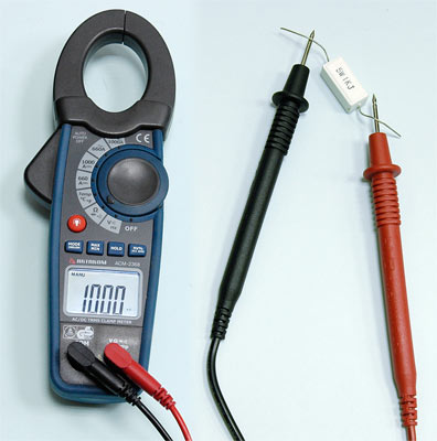
- Insert the black test lead into the negative COM terminal and the red test lead into the V·Ω·TEMP·Hz positive terminal
- Set the function switch to the Ω position
- Touch the test probe tips across the circuit or component under test
- Read the resistance on the LCD display.
Temperature Measurements
- Set the function switch to the TEMP position.
- Insert the Temperature Probe into the negative COM and the V·Ω·TEMP·Hz· positive jacks, observing polarity.
- Touch the Temperature Probe head to the device under test. Continue to touch the part under test with the probe until the reading stabilizes.
- Read the temperature on the display. The digital reading will indicate the proper decimal point and value.
- Use the MODE button to select ºF or ºC.
WARNING: To avoid electric shock, be sure the thermocouple probe has been removed before changing to another measurement function.


